Investigators: Kamran Asim, Jaewon Lee
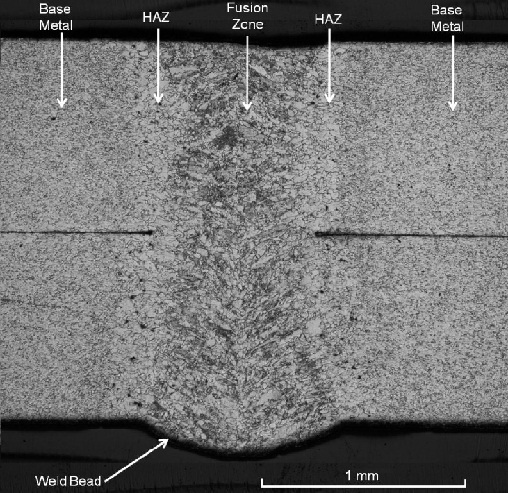
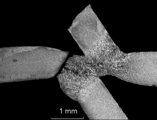
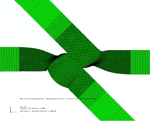
Laser welding has been used widely in the industry because of its advantages such as narrow heat affected zone, small residual stress and distortion, and relatively high welding speed. A lap joint is one of common weld joints in laser welding due to its relative less restricted tolerance requirement. Due to the geometry of a lap joint, natural cracks or notches are presented at the edges of the weld bead. Figure 1 shows a micrograph of the cross section of a laser weld. Micro-hardness tests were used to determine the hardness values of the base metal, heat affected zone and weld metal. Figure 2 shows a cross sectional micrograph of a failed specimen after static test. The lap-shear load stretches the upper right leg and the lower left leg as shown in the figure. Figure 3 shows the deformed shape of the laser weld from a finite element analysis with consideration of the different material properties in the base metal, heat affected zone and the weld metal.

Figure 1. A micrograph of the cross section of a laser weld.

Figure 2. A cross sectional micrograph of a failed specimen after static test.

Figure 3. The deformed shape of the laser weld due to the necking near the final failure stage from a finite element analysis.
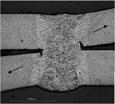
Fatigue cracks as shown in Figure 4 usually are initiated from the natural cracks or notches of lap joints under cyclic loading conditions. A fatigue crack growth model based on the analytical local stress intensity factor solutions of kinked cracks and the Paris law for crack growth is then adopted to estimate the fatigue lives of the laser welds in lap-shear specimens under cyclic loading conditions.

Figure 4. Cross sectional micrograph of partially failed laser weld.
